Failed project: Digital negative delay in RF matching
Published:
Given that time is always measured positively, ADS or other simulator can give a negative delay block in math. What does a negative delay in a circuit mean? A negative delay circuit/block could perfectly solve the wide band matching phase rotation issue.
Introduction. Negative delay could remove frequency-dependent wide band load-matching issues, and if achieved, the impact could be huge. However, in reality, L/C/line components all have positive delay. In the past, many of us have tried to use a network’s positive phase vs. frequency feature to achieve negative delay, but all attempts have failed with significant insertion loss.
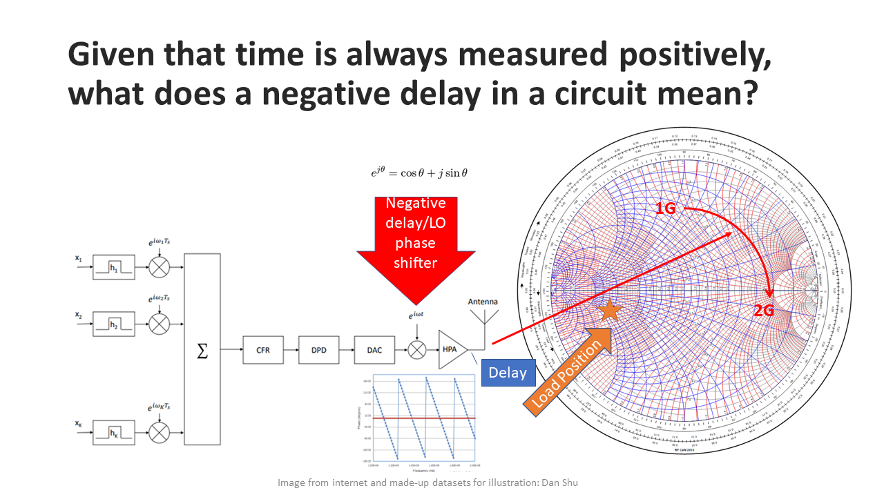
1. What if we could achieve negative delay from a signal source using a digital approach, such as an FFT-based phase shift algorithm? I have tried a few ideas, but they all failed. The reason for my failure is that traditional FFT approaches can only manipulate I/Q amplitude and phase with voltage. However, the RF matching challenge lies in the fact that there is a phase shift between I and V due to impedance Z = R + jX. The reactance of Z shifts the V/I phase, which makes power delivery from point A to point B less efficient. In the worst case, 100% reflection could occur. So my first attempt at using an FFT approach to solve the matching issue failed.
 pic1 Failed idea, digital pre-delay at LO/Mixer stage
2. The next step idea.

pic2 thinking…
========================
